

RNS Venture

Blog

Your blog category

Blog

What Is a CCTV System and How Does It Work?

What Is a CCTV System and How Does It Work? In an era where security and real-time monitoring are paramount, Closed-Circuit Television (CCTV) systems have transitioned from luxury commercial installations to essential everyday infrastructure. Whether safeguarding suburban homes, monitoring bustling retail lanes, or protecting sprawling industrial complexes, CCTV serves as the silent sentinel of modern surveillance. Unlike traditional broadcast television, which transmits signals openly to the public, a CCTV system operates on a restricted, private loop. The video signals are captured, transmitted, and displayed only to a designated group of authorized monitors and recording devices. This closed-ecosystem design ensures confidentiality, integrity, and absolute control over the visual data being gathered. To fully appreciate the value of modern video surveillance, it is crucial to understand the underlying mechanics that power these systems. This guide dives deep into the architecture, components, and workflows of a CCTV system, analyzing how they operate across eight core dimensions. 1. The Core Architecture: Understanding the “Closed-Circuit” H4: The Closed Loop Philosophy The defining characteristic of any CCTV system is its “closed” nature. In a standard broadcast system, signals are sent over the airwaves or via satellite to any receiver calibrated to the correct frequency. In contrast, a CCTV system forms a dedicated, private loop. The cameras, transmission lines, recording devices, and displays are physically or digitally linked together directly. Without direct access to this private network, external parties cannot intercept or view the video feed. This foundational architecture ensures that sensitive footage—whether of a banking hall, a private residence, or a high-security research laboratory—remains accessible only to authorized personnel. H5: Key Components of the Network At its most basic level, a CCTV system relies on a clean, uninterrupted chain of data flow. This chain consists of four indispensable components: The Input (Cameras): Capture the physical environment and convert light into electronic signals. The Medium (Cables or Wireless Networks): Transport the video signals from the camera to the processing hub. The Processor/Recorder (DVR or NVR): Receive, compress, index, and save the incoming footage onto storage drives. The Output (Monitors & Interfaces): Reconstruct the processed digital signals back into viewable video for security personnel. 2. Camera Modalities and Image Capture H4: Digital (IP) vs. Analog Cameras The starting point of any surveillance system is the camera itself, which generally falls into one of two technological eras: Analog or Internet Protocol (IP). Legacy analog cameras capture a continuous analog wave signal and transmit it over coaxial cables to a central station. While reliable and simple to configure, analog systems are limited in resolution. Modern IP cameras, on the other hand, are essentially mini-computers. They capture images, digitize them on-board, compress the files, and transmit them as packetized data over an IP network. This digital architecture allows IP cameras to deliver incredibly high resolutions, ranging from 1080p Full HD to ultra-detailed 4K and beyond. H5: Lenses, Sensors, and Resolution An image begins when light passes through the camera’s lens and hits an electronic image sensor—typically a Charged-Coupled Device (CCD) or a Complementary Metal-Oxide-Semiconductor (CMOS) sensor. The sensor’s job is to convert photons (light) into an electrical charge. The quality of this conversion determines the clarity of the footage. Higher megapixel (MP) sensors capture more visual data, allowing security teams to zoom in on recorded footage to read license plates, identify faces, or verify small details without the image pixelating. Additionally, cameras can feature fixed lenses (for a constant field of view) or varifocal lenses (which allow manual or motorized adjustment of focal length and zoom). 3. Transmission Mediums: How the Signal Travels H4: Wired Transmission (Coaxial and Ethernet) Once a camera captures a frame, that signal must travel to the recording and monitoring station. In traditional analog systems, this is achieved using heavy-duty coaxial cables (such as RG59), which transfer raw electrical signals directly. In modern digital IP systems, transmission is handled by Ethernet cables (such as Cat5e, Cat6, or Cat7). Ethernet cables transport digital packets of data over long distances with minimal interference. For massive industrial campuses where distances exceed the 100-meter limit of standard copper Ethernet cabling, fiber-optic cables are deployed, transmitting data using pulses of light to guarantee zero lag and immune-to-interference feeds. H5: Wireless Transmission and IP Networks For locations where drilling walls or laying miles of physical cable is impractical—such as historic buildings, parking lots, or temporary construction sites—wireless CCTV transmission is utilized. Wireless IP cameras connect directly to a facility’s local Wi-Fi router or dedicated point-to-point wireless bridges. The video stream is transmitted over radio frequencies (typically 2.4 GHz or 5 GHz bands). While highly convenient and flexible, wireless transmission requires a robust network infrastructure to prevent signal drops, latency issues, or interference from other wireless devices operating nearby. 4. Recording and Storage Technologies (DVR vs. NVR) H4: Digital Video Recorders (DVR) In analog and hybrid systems, the physical cables from the cameras terminate at a Digital Video Recorder (DVR). Because analog cameras send raw, uncompressed electrical waveforms, the DVR’s primary job is to digitize these signals first. The DVR contains a capture card that processes the analog feed, compresses it using modern codecs (like H.264 or H.265), and writes the digital files onto internal hard drives. Because the processing occurs centrally at the DVR unit, the cameras themselves remain relatively inexpensive and simple. H5: Network Video Recorders (NVR) & Cloud Storage In an IP-based camera setup, the central hub is a Network Video Recorder (NVR). Since IP cameras compress and digitize the video feed directly on-board, they send a finished digital stream over the local network. The NVR’s role is not to digitize the video, but rather to receive, sort, and store these pre-processed digital streams onto hard disks. This offloads the processing workload from the central machine, allowing NVR systems to manage significantly higher resolutions and frame rates. Furthermore, modern NVRs can mirror their recordings to secure cloud storage, providing off-site redundancy in case the physical recorder is stolen or damaged during a break-in. 5. The Viewing and Monitoring Interface H4:

Blog

What Are Access Control Systems & How Do They Work for Offices?

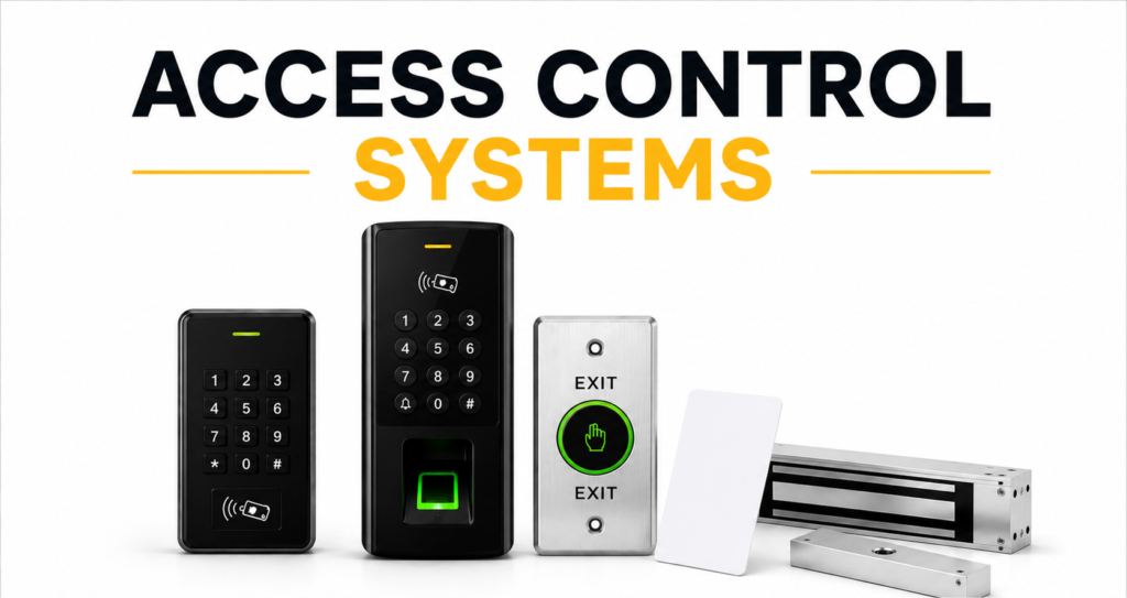
What Are Access Control Systems & How Do They Work for Offices? Modern office environments have evolved far beyond the classic lock-and-key system. As workplaces grow, manage hundreds of staff, adopt flexible shifting schedules, and house valuable intellectual and physical property, security infrastructure must adapt. Today’s commercial office buildings require a dynamic, automated framework that keeps unauthorized people out while letting verified employees flow through seamlessly. This is exactly what an Access Control System does. At its core, an office access control system is a digital and physical security network designed to regulate who can enter specific zones of a building, and when. From high-throughput main lobbies to sensitive server rooms, these systems replace physical keys with digital credentials—such as smart cards, smartphone apps, or biometric scans. They log every movement, integrate with fire alarms for safety, and automate HR attendance tracking. Here is a deep dive into how these systems operate, how their individual components connect, and how they protect the modern office.     1. The Core Hardware Architecture and Wiring H4: The Edge Devices: Readers and Electronic Locks The physical footprint of an office access control system consists of specialized hardware installed at every monitored doorway. The most visible component is the credential reader mounted adjacent to the door frame on the unsecure side. The reader constantly awaits an input—such as an RFID card tap, a biometric scan, or a mobile Bluetooth ping. On the door itself, a heavy-duty electronic locking mechanism is installed. This is typically a magnetic lock (maglock), which uses a strong electromagnet to hold the door frame shut with up to 1,200 pounds of force, or an electric strike, which replaces the standard mechanical door faceplate and releases the latch when energized. H5: The Central Controller and Communication Converter Behind the scenes, tucked away in an IT closet, is the access control panel or controller. This acts as the brain of the local network. All readers, electronic locks, and exit devices (like motion sensors or push-to-exit buttons) are physically wired directly back to this control board. When a user presents a credential, the reader sends raw data down the wire to the controller. The controller processes this data, decides whether to grant access, and commands the electronic lock to release. To manage the entire facility from a desktop, a communication converter or network interface translates the controller’s serial signals into TCP/IP protocol, allowing the system to communicate directly with an office computer or cloud server. 2. The Step-by-Step Authentication Workflow H4: Requesting Access at the Reader The workflow of gaining access is designed to happen in milliseconds. It begins when an employee approaches a locked door and presents their credential. The reader captures the raw credentials—such as reading the microchip inside an RFID card or mapping the minutiae points on a fingerprint sensor. This raw analog signal is instantly digitized and encrypted on-board to prevent “sniffing” or intercepting. It is then forwarded as a unique identification packet to the door controller. H5: Decision Processing and Lock Relaying Once the controller receives the digitized ID packet, it checks its localized database to see if this specific user has clearance. The controller evaluates multiple conditions: is the card active? Is the user allowed through this specific door? Is it during their scheduled shift hours? If all checks pass, the controller activates an onboard electric relay. This relay momentarily interrupts or redirects the power supply going to the door’s magnetic lock or electric strike. The lock clicks open, the user walks through, and a magnetic door closer swings the door shut, re-engaging the lock. 3. The Spectrum of Access Credentials H4: From Physical Tokens to Mobile Access Office facilities can utilize several different types of credentials depending on their budget and security goals. The most traditional is the RFID Proximity Card or Key Fob. These are highly affordable and simple to hand out, though they suffer from the risk of being lost, cloned, or shared among employees. To counter this, many modern tech companies are transitioning to Mobile Access Control. This system turns an employee’s smartphone into their key using secure apps that communicate with the wall readers via Bluetooth Low Energy (BLE) or Near Field Communication (NFC). H5: Biometric Verification and Multi-Factor Terminals When security cannot be compromised, offices pivot to Biometric Access Control. Biometric systems rely on the unique physical characteristics of the user—most commonly facial recognition, fingerprint templates, or iris structures. Because you cannot lose or share your physical face or fingerprint, biometrics eliminate “buddy punching” (where employees clock in for each other) and prevent unauthorized badge transfers. For extreme high-security zones like research labs or server closets, Multi-Factor Authentication (MFA) is deployed, requiring a user to tap an RFID badge and pass a biometric facial scan before entry is permitted. 4. Central Software Management and Databases H4: The Administrator Dashboard While the physical controllers make the split-second decisions at each door, the entire system is orchestrated through centralized Video and Access Control Management Software. From a secure computer console, facilities managers and IT administrators can oversee the entire facility’s security map. The software provides a real-time activity feed: showing exactly who is entering which door, flagging doors that have been left propped open, and generating automated daily or weekly occupancy reports. H5: Real-Time Roster Synchronization and Access Levels The core benefit of centralized software is the ability to easily manage “Access Groups.” Instead of configuring doors one by one, administrators create profiles. For example, a “Marketing Team” profile can be configured with access only to the main lobby, marketing office, and cafeteria during weekdays. If a marketing executive leaves the company, an administrator can delete their profile in the software, and that digital command instantly propagates across all door controllers across the entire office network, immediately revoking access without having to collect a physical key. 5. Integration with HRMS and Payroll Systems H4: Automated Time and Attendance Logging Modern office access control systems are far more than just security barriers; they

Scroll to Top