

IP CCTV Camera Installation
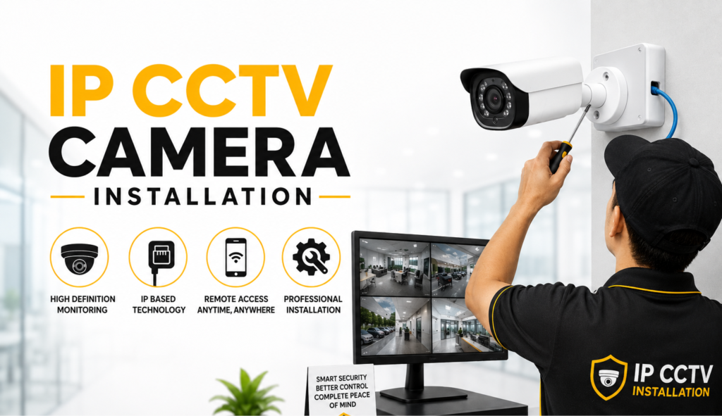
Upgrading your security infrastructure with an Internet Protocol (IP) CCTV system is one of the most effective ways to protect your office or home. Unlike legacy analog systems that require separate coaxial and power lines, modern IP systems simplify installation using Power over Ethernet (PoE). A single Ethernet cable (Cat5e or Cat6) carries both high-speed digital video and electrical power directly from your network network switch or Network Video Recorder (NVR) to the camera.
Whether you are a hands-on IT professional configuring a corporate network or setting up a local office security loop, installing an IP camera system requires careful planning, robust wiring, and precise network configuration. This guide outlines the end-to-end installation process, from physical mounting to digital setup.
1. Pre-Installation Planning and Camera Placement
H4: Determining Camera Angle and Field of View
Before drilling any holes, map out your camera locations on a floor plan. Standard dome cameras are ideal for indoor ceilings and wide-angle room views, while bullet cameras are designed for highly visible, directional outdoor perimeters. Ensure your cameras are placed high enough (typically 8 to 10 feet) to prevent tampering or physical vandalism, but low enough to capture clear facial features. Focus on primary entryways, corridors, parking lot exits, and valuable assets like server closets or safes.
H5: Lighting Considerations and Glare Mitigation
Be highly mindful of light sources. Avoid pointing your cameras directly at large windows, streetlights, or highly reflective surfaces. Direct sunlight or oncoming headlights can cause severe glare and trigger the camera’s wide dynamic range (WDR) settings, potentially turning your target subject into a dark silhouette. For outdoor perimeters, ensure the camera’s infrared (IR) night-vision LEDs will not reflect directly off nearby walls or tree leaves, which can blind the sensor in total darkness.
2. Essential Tools and Hardware Checklist
H4: Cabling and Structural Hardware
Ensure you have all physical components prepared before starting the installation:
IP Cameras: Selected based on resolution (4MP or 4K), lens focal length, and form factor.
Network Video Recorder (NVR): With a pre-installed surveillance-rated hard drive (HDD).
Cat5e or Cat6 Ethernet Cables: Solid copper conductor cables are highly recommended for PoE stability over long distances.
RJ45 Connectors & Crimping Tool: For terminating custom-length cable runs.
Outdoor Junction Boxes: To protect cable joints and pigtails from moisture and weather.
H5: Power and Networking Equipment
Because IP systems are network-centric, you must choose your power delivery method. If you are using a PoE NVR, the cameras can plug directly into the ports on the back of the recorder. If you have an standard NVR, you will need a PoE Network Switch or individual PoE Injectors to sit between your main router and the camera, injecting electrical power directly into the Ethernet line.
3. Running and Terminating the Cable Network
H4: Pulling Cable Through Walls and Ceilings
Start by running your Cat5e or Cat6 cables from your centralized NVR/Switch location to each designated camera endpoint. Keep network runs under 100 meters (328 feet), as copper cabling experiences data packet loss and voltage drop beyond this distance. If running cables through walls or drop ceilings, avoid running them parallel to high-voltage AC electrical lines (such as 110V or 220V power lines), as electromagnetic interference can disrupt your camera feeds. Keep a minimum of 12 inches of separation from power cables wherever possible.
H5: Crimping RJ45 Connectors (T568B Standard)
Once the cables are in place, strip back the outer jacket about an inch and untwist the internal wire pairs. Arrange the wires according to the industry-standard T568B color code:
White-Orange, 2. Orange, 3. White-Green, 4. Blue, 5. White-Blue, 6. Green, 7. White-Brown, 8. Brown.
Insert the ordered wires into an RJ45 connector, ensuring they reach all the way to the tip, and crimp them firmly with your crimping tool. Test both ends of the cable with a basic RJ45 network tester before mounting the camera to ensure there are no open splits or shorts.
4. Mounting and Physical Camera Installation
H4: Securing the Mounting Bracket
Place the camera’s mounting template or bracket against the wall or ceiling. Mark the screw holes with a pencil. If mounting on drywall, drill pilot holes and insert plastic anchors to support the weight of the camera. If mounting on concrete or brick, use a masonry bit and wall plugs. Feed the terminated RJ45 cable through the center of the bracket or through a side-access conduit cutout.
H5: Weatherproofing Outdoor Connections
For outdoor camera installations, water ingress is the number one cause of hardware failure.
Always install an outdoor junction box to house the delicate camera pigtail connector.
Wrap the RJ45 connection with self-amalgamating waterproof tape, or slide the waterproof gland (included with most IP cameras) over the Ethernet jack before clicking it in place.
Create a drip loop (a downward curve in the cable just before it enters the camera or junction box) to ensure rainwater flows down off the loop instead of following the wire directly into the device.
5. Connecting to a PoE Injector or Switch
H4: Setting Up a PoE Injector for Single Cameras
If you are integrating a standalone IP camera into an existing non-PoE office network, you can use a compact PoE Injector.
To set this up, connect a standard Ethernet cable from your non-PoE network router to the port labeled “LAN” or “Data In” on the injector. Then, run a second Ethernet cable from the port marked “PoE” or “Power + Data Out” directly to the IP camera. Plug the injector’s power cord into a wall outlet to deliver power directly through the line.
H5: Connecting to a Multi-Port PoE Switch
For systems with four or more cameras, a dedicated PoE Network Switch is the most efficient choice. Run all of your camera lines directly into the PoE-enabled ports on the switch. Then, run a single “uplink” Ethernet cable from the switch to your main network router. This consolidates all of your camera bandwidth onto a single high-speed network line and allows you to manage the power supply of all cameras from a central point.
6. Network Configuration and IP Assignment
H4: Accessing the Camera’s Web Interface
By default, new IP cameras ship with a static manufacturer IP address (e.g., 192.168.1.64). To configure the camera, connect a computer to the same local network subnet. Open a web browser, type the camera’s default IP address into the URL bar, and press Enter. You will be prompted to set a strong, unique administrator password on your first login.
H5: Configuring Static IP vs. DHCP
Once inside the camera’s settings menu, navigate to the Network Settings tab. For surveillance systems, it is highly recommended to assign each camera a Static IP address outside of your router’s DHCP pool range. This ensures that even if your router restarts or loses power, the NVR will always be able to locate the cameras at their exact assigned IP address, preventing “Video Loss” errors. Alternatively, you can use DHCP and configure IP reservation on your main router’s settings.
7. Pairing Cameras with the Network Video Recorder (NVR)
H4: Adding Cameras to the NVR
If you are using a plug-and-play PoE NVR, simply plugging the cameras into the ports on the back of the unit will automatically register them. If your NVR is on a different network switch, log into your NVR’s dashboard via its attached monitor or web client. Navigate to the Camera Management page and click “Search” or “Auto-Detect.” The NVR will scan the local subnet and list all discovered IP cameras.
H5: Inputting Credentials and Syncing Video Streams
Select the discovered cameras and click “Add.” You will need to input the exact administrator username and password you created for each camera during step 6. Once verified, the NVR will establish a secure connection to the camera’s video stream using ONVIF (Open Network Video Interface Forum) or the manufacturer’s proprietary protocol. The camera’s live view will then appear on your NVR screen.
8. Adjusting Settings and Final Commissioning
H4: Configuring Motion Detection and Recording Schedules
With the live feeds active, configure your recording preferences. Navigate to the NVR’s Storage Settings and set up your recording schedule. To maximize hard drive storage space, configure the system to record continuously in low-resolution (sub-stream) but switch to full resolution (main-stream) when motion detection or AI analytics (such as human or vehicle detection) are triggered.
H5: Setting Up Remote Mobile Monitoring
To view your cameras on the go, connect your NVR’s WAN network port directly to your internet router. Download the manufacturer’s official secure mobile app on your smartphone. Locate the P2P QR Code in your NVR’s network menu, scan it using the app, and log in with your NVR credentials. You can now securely stream real-time, high-definition footage of your office or home from anywhere in the world.
Installation Troubleshooting Guide
| Issue Encountered | Likely Cause | Step-by-Step Resolution |
| No Power / Camera LED Off | Loose connector or bad RJ45 crimp | Re-test the Ethernet cable using a physical network tester. |
| Camera Keeps Rebooting | Voltage drop or insufficient PoE power | Ensure you are using solid copper Cat6 cables, or check if the PoE switch has enough wattage budget. |
| “Video Loss” on NVR Screen | IP Address conflict or changed IP | Log into the camera via a web browser, verify its static IP, and re-add it to the NVR camera list. |
| Blurry or Foggy Night Footage | IR reflection or dirty lens dome | Clean the lens glass with a microfiber cloth; ensure the camera is not reflecting off close walls. |
Conclusion
Installing a modern IP CCTV camera system provides a powerful security safeguard for your business or home. By leveraging the simplicity of Power over Ethernet (PoE) and the high bandwidth of digital networking, you can capture crystal-clear 4K footage, automate recording triggers through AI motion analytics, and monitor your facility remotely with ease.
Taking the time to route your Cat6 cables correctly, terminate your RJ45 connections cleanly, and assign dedicated static IP addresses ensures that your surveillance network remains highly reliable, resilient to outages, and easily scalable as your security needs expand.